Hi there !
Last summer, while I was visiting the Urchin crew during my summer trip, I’ve spent a few days working on Tube in the nerdodrome. With Bassam, we had a discussion about cracks generation for the timelapse sequence. The environment for Wires for Empathy is mainly composed of concrete and we thought it would be kind of cool to have some nice cracks growing on the walls. Generating cracks is not that hard, we can do procedurally, with some great results. This tutorial explains how to do it fairly simply.
However, animating the cracks is a little bit harder and we cannot rely on the procedural method any more. We searched for examples and papers of people who already worked on this problem and found some great material. Unfortunately, most of the papers we found where based on heavy research and would include some serious C/C++ coding in order to have these tools inside Blender.
The python approach
Our first idea was to write an OSL shader that could generate cracks with some growing parameters that artists could use to control the speed and shapes of the cracks. Moreover, our rendering pipeline is entirely CPU based so using some OSL would be a problem. I’m sure it is doable in OSL, but I don’t know this language at all and even though I’m willing to learn this shading language, I would have spent a lot of time of time learning it, without being sure that I could achieve the result I wanted.
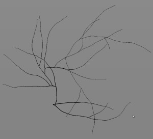
So I chose to use Python and to create a script that would manipulate Bezier curves to generate cracks in a procedural fashion. The generation algorithm is fairly simple and a based on a “branch” approach. Complex cracks can be splited into small simple “branch” that can be easily generated and manipulated. To do so, we have a very basic recursive algorithm that create a branch a determine the position of its children on it. We then repeat the branch generation on the children and determine its ow children and so on. The following image shows how a complex cracks can be seperated into those branches.

Branch Generation
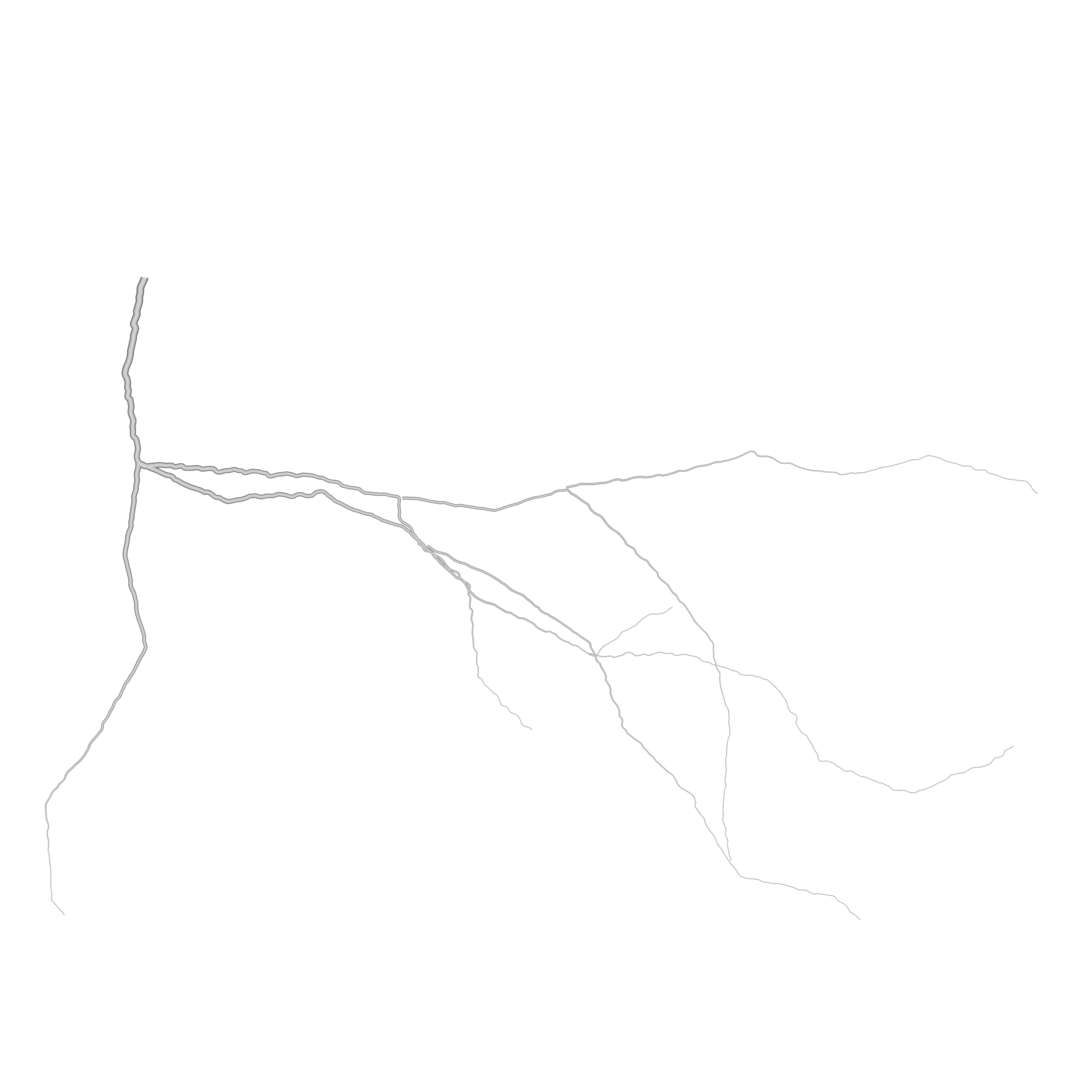
The following image explains our approach to approximate the shape of a crack. We can see that crack can be split into big segments (in blue) that can be split again into smaller segments (in red).
 In Blender, we define a general direction for the branch, and generate points along it with small angle variations between each point. By default, every 5 points generated, we created a bigger angle variation (corresponding to the blue one in the image). We then convert theses points to a Curve Object.
Children Generation
 When each point is generated, we generate a random value between 0 and 1 and look if this number is smaller than the Children Probability defined by the User. If it’s the case, we create a child branch at the point position and store it’s relative position on the master branch. For example, if the tenth point of a branch composed of forty points has a children branch, we create this new branch with a ‘relative position in the master branch’ of 25%. This will be very useful when dealing with the animation.
As the algorithm for branch generation is recursive, we need a way to stop it. To do so, we simply decrease the child probability at every generation, so each generation of children is ten times less likely to have children than its parents.
More displacement on cracks
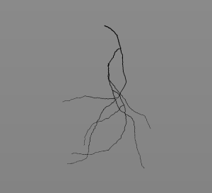
The previous image shows how, even if we have generated cracks with big angle values, it still appears too smooth. We need to add more displacement on the cracks. To do so, we subdivide each curve several times, select randomly some points on it and move them using the proportional editing tool with a random falloff. After some test, we found out that we have much better result by repeating this operation with small values several times instead of doing it in one go.
The result is far more convincing with little displacement along the cracks. However, this step currently produce a small but annoying bug where some roots of some children branch get disconnected from their parent because they are displaced under the effect of the proportional editing tool. This bug is currently being fixed.
Animation
The animation system is fairly simple, we key the End Bevel Factor parameter to animate the growth of a branch. However, by doing such, the growth is very linear and robotic. So, we have added a parameter to control the speed of growth and make it randomly go faster and slower during its generation. We simply subdivide the F-Curve for animation and change the position of the keys in the Y axis as illustrated in the following image :

Results !
The result is visible is the following video :
The script is used to generate the cracks and their animation as you can see in the following video. We use custom attenuation and displacement on cracks to get a more believable result.
In order to make cracks interact with other object and surface, we need to export it as a sequence of images with transparent background. We will then be able to plug this sequence into a material or a modifier in the scene and generate cracks easily in the scene. On the left we have an example of one of these image. To render it, we simply do an OpenGL Render from the top view with an orthogonal camera. We also have applied a simple material with a black&white colorRamp so we can destroy the edge of the cracks later on.
The image sequence is then used in the scene file, as a factor for displacement modifier on a highly displaced plane and as a mix Factor on the concrete material. As we have loaded an image sequence, we only have to set the right number of frames to use and Blender will automatically refresh the image number to match the current frame and we have our animated crack !
Todos and limitations
Currently, the tool is very limited and could be largely improved by adding new features like cracks generation snapped directly on a 3D surface. This is doable as we first generate a point cloud, we could snap each point on the target surface as we generate them.
One of the biggest limitation is the fact that we don’t have access to all the modifiers we want as we manipulate curves. For example, we don’t have access to dynamic painting or boolean modifiers. Keep in mind that this a tool to generate background and secondary animation in some timelapse sequence. Our needs are quite limited and our plan is to generate a few different cracks that artists can then plug easily into their scene and add some details without spending days with painting cracks manually.
Download
The script can be download here. For now, it is only a script, so you’ll have to load the file in the blender text editor and run the script from here. Cracks Generator is added as a new tab in the tool-shelf of the 3D View.